April 10th, 2024
The Project
The objective of this project was to develop a microcontroller-based device capable of rapid 3D spatial mapping. Using a Time-of-Flight (ToF) sensor attached to a stepper motor, the device achieves precise 360° spatial scanning and visualizes the captured data using Python libraries and PC connectivity.
My Role
This project was completed entirely independently. My responsibilities included programming the ARM architecture-based microcontroller, wiring and connecting the hardware, and conducting thorough testing.
Key Features
-
Rapid 3D Spatial Mapping: Utilizes the VL53L1X ToF sensor for precise distance measurements up to 4 meters, with a high ranging frequency of up to 50Hz.
-
Intuitive Operation: Features a simplified user interface with dedicated buttons for starting and resetting the scanner.
-
Full 360° Scanning: Employs a 28BYJ-48 Stepper Motor with 2048-step precision, controlled in Full Step mode, for accurate positioning and smooth operation.
-
Advanced Data Capture: Ensures efficient I²C communication for seamless data transfer and enhanced data capture.
-
PC Connectivity: Establishes serial communication with a Python interface for easy data transfer and visualization.
-
Microcontroller Efficiency: Powered by an MSP432E401Y microcontroller operating at 60MHz for optimized performance.
Programming the Microcontroller
The microcontroller and its functionality were programmed in C using the Keil software development environment, designed specifically for ARM Cortex-M based microcontroller devices. The program instructs the microcontroller to wait for a button input and then rotate the stepper motor 360°. Every 11.25°, the ToF sensor takes a scan. On the next button input, the stepper motor rotates 360° in the opposite direction, taking scans at the same intervals. Here is a large portion of the code used.
            //*************************************************//
            //*************** Output Function *****************//
            //*************************************************//

            // Variable Definitions
            int on = 0;                   	// Variable to determine if user wants to start scan, 1 to start scan
            int CW = 1;                   	// CW = 0 means clockwise, CW = 1 means counter clockwise
            uint16_t z_coord = 0;               // Initial z coordinate that will be changed after every full scan
            uint16_t z_interval = 100;	  	// Z interval is defined by the distance change after each step in mm [CHANGE FOR NEW INTERVAL]
            float degree = 0;		        // Degree value that is changed every measurement

            while(1) {
                int input = GPIO_PORTM_DATA_R &= 0xF;
                if((input) == 1){
                SysTick_Wait10ms(5);
                while((GPIO_PORTM_DATA_R &= 0xF) != 0){}
                if((input & 0b00000001)==1){		// Use polling to check for button input
                  if (on==0){				// If on == 0, set on = 1, and vice-versa
                    on = 1;
                  } else {
                    on = 0;
                  }
                }
                SysTick_Wait10ms(5);
              }
              if ((on==1)){ // if on and step count is less than 360 degree rotation
                int rotation_Step = 512;
                GPIO_PORTF_DATA_R ^= 0b00010000; // Turn on PF4 LED (indication that currently in scan)
                if (CW == 0){
                  // Clockwise
                  degree = 0;
                  for (int i=0; i<=rotation_Step; i++){	// rotate for 360 degrees
                    uint32_t delay = 1;

                    if((i%(rotation_Step/32)) == 0){ 	// If at 11.25 degrees, measure distance
                      GPIO_PORTF_DATA_R ^= 0b00000001; 	// Turn on PF0 LED (indication that measurement is being taken)
                      GPIO_PORTF_DATA_R ^= 0b00000010; 	// Turn on PF1 for bus speed inspection

                      status = VL53L1X_GetDistance(dev, &Distance);	// Capture measured distance value

                      status = VL53L1X_ClearInterrupt(dev); // Clear interrupt has to be called to enable next interrupt

                      // print the resulted readings to UART [Distance, Z Coordinate, Degree]
                      sprintf(printf_buffer,"W,%u,%u,%f\r\n", Distance, z_coord, degree);
                      UART_printf(printf_buffer);
                      degree += 11.25;
                    }

                    // Spin motor
                    GPIO_PORTH_DATA_R = 0b00000011;
                    SysTick_Wait10ms(delay);
                    GPIO_PORTH_DATA_R = 0b00000110;
                    SysTick_Wait10ms(delay);
                    GPIO_PORTH_DATA_R = 0b00001100;
                    SysTick_Wait10ms(delay);
                    GPIO_PORTH_DATA_R = 0b00001001;
                    SysTick_Wait10ms(delay);

                    if((i%(rotation_Step/32)) == 0) {
                      GPIO_PORTF_DATA_R ^= 0b00000001; 		// Turn off PF0 LED
                      GPIO_PORTF_DATA_R ^= 0b00000010; 		// Turn off PF1 for bus speed
                    }
                  }
                    CW = 1;		// Switch directions
                } else {
                  // Counter Clockwise
                  degree = 348.75;
                  for (int i=0; i<=rotation_Step; i++){		// rotate for 360 degrees
                    uint32_t delay = 1;

                    if((i%(rotation_Step/32)) == 0){ 	// If at 11.25 degrees, measure distance
                      GPIO_PORTF_DATA_R ^= 0b00000001; 	// Turn on PF0 LED (indication that measurement is being taken)

                      status = VL53L1X_GetDistance(dev, &Distance);	// Capture measured distance value

                      status = VL53L1X_ClearInterrupt(dev); // Clear interrupt has to be called to enable next interrupt

                      // print the resulted readings to UART [Distance, Z Coordinate, Degree]
                      sprintf(printf_buffer,"W,%u,%u,%f\r\n", Distance, z_coord, degree);
                      UART_printf(printf_buffer);
                      degree -= 11.25;
                    }

                    // Spin motor
                    GPIO_PORTH_DATA_R = 0b00001001;
                    SysTick_Wait10ms(delay);
                    GPIO_PORTH_DATA_R = 0b00001100;
                    SysTick_Wait10ms(delay);
                    GPIO_PORTH_DATA_R = 0b00000110;
                    SysTick_Wait10ms(delay);
                    GPIO_PORTH_DATA_R = 0b00000011;
                    SysTick_Wait10ms(delay);

                    if((i%(rotation_Step/32)) == 0) {
                      GPIO_PORTF_DATA_R ^= 0b00000001; 	// Turn off PF0 LED
                    }
                  }
                  CW = 0;				// Switch directions
                }
                GPIO_PORTF_DATA_R ^= 0b00010000;        // Turn off PF4 LED
                on = 0;					// Turn off
                z_coord += z_interval;	              	// Adjust z coordinate
              }
            }
UART and Python Integration
Via UART communication, the PC can read the output from the microcontroller. A Python program then manipulates this data. The microcontroller sends each scan's data in the format [Distance, Z Coordinate, Degree], where the distance is the measurement from the ToF sensor to a surface, and the Z Coordinate is the horizontal displacement from the last scanned spot. The Python program uses the Open3D library to create a point cloud from the scan data, constructing a visual representation by connecting each frame with lines. This segment of the final program below covers the UART communication with the microcontroller.
            #   Final Program
            #   Written by Ayaan. K
            #   2024-04-01

            import serial
            import math
            import numpy as np
            import open3d as o3d

            filename = "coordinates.xyz"

            s = serial.Serial()
            s.baudrate = 115200
            s.port = 'COM3'
            s.timeout = 10
            s.open()

            print("Opening: " + s.name)

            # reset the buffers of the UART port to delete the remaining data in the buffers
            s.reset_output_buffer()
            s.reset_input_buffer()

            # wait for user's signal to start the program
            input("Press Enter to start communication...")
            # send the character 's' to MCU via UART
            # This will signal MCU to start the transmission

            s.write(b's')

            data = []
            matchflag = True
            setsOfScan = 3   # change depending on how many scans going to do, 3 for demo
            w_count = 0
            # recieve characters from UART of MCU
            while (matchflag == True):
                x = s.readline()                    # read one byte
                dec = x.decode()
                print(dec)
                if (len(dec)>0):
                    if (dec[0] == 'W'):             # if leading character is 'W' add to data array
                        data.append(dec)
                        w_count += 1
                    if (dec[0] == "X"):             # if want to implement stop button in the future
                        matchflag = False
                if (w_count == (setsOfScan*32)):
                    matchflag = False
            # the encode() and decode() function are needed to convert string to bytes
            # because pyserial library functions work with type "bytes"

            #close the port
            print("Closing: " + s.name)
            s.close()
This segment covers the data manipulation into readable point cloud data for Open3D.
              print(data)

              # Parse each item in data array to get [Distance, Z Coordinate, Degree]
              pcoords = []
              for item in data:
                  subitem = item.split("\r")
                  coord = subitem[0].split(",")
                  pcoords.append([int(coord[1]), int(coord[2]), float(coord[3])])

              print(pcoords)

              # Create new array and add [x,y,z] coordinates for each point
              coords = []
              for coord in pcoords:
                  print("Degree: ", coord[2])
                  temp = [coord[0]* math.cos(math.radians(coord[2])), coord[0] * math.sin(math.radians(coord[2])), coord[1]]
                  coords.append(temp)

              print(coords)

              # Flip every odd set because every odd set is taken in a different direction
              # Iterate over the list in steps of 32
              for i in range(0, len(coords), 32):
                   # Check if the current set is odd
                  if i // 32 % 2 == 1:  # If the index divided by 32 has a remainder of 1, it's an odd set
                      # Reverse the sublist of 32 values
                      coords[i:i+32] = reversed(coords[i:i+32])

              print(coords)

              f = open(filename, "w")

              # Write data to .xyz file
              for coord in coords:
                  f.write("{x} {y} {z}\n".format(x = coord[0], y = coord[1], z = coord[2]))
              f.close()

              print("Done")
This final segment is the Open3D processing of the data and the creation of the visual render.
            # Get Point cloud data from file
            point_cloud_data = o3d.io.read_point_cloud(filename, format="xyz")

            # Print out data to make sure it exists
            print("Point cloud array: ")
            print(np.asarray(point_cloud_data.points))

            # Display the data
            print("Spawining separate window with point cloud: ")
            o3d.visualization.draw_geometries([point_cloud_data])


            # Define connections
            lines = []
            y = 0
            num_scans = 32
            for x in range(len(coords)):
                print(y, ((len(coords)/num_scans)-1))
                if (((x+1)%num_scans) != 0) or (x==0):
                    print("General case: ", x)
                    lines.append([[x], [x+1]])
                else:
                    print("Special Case: ", x)
                    lines.append([[x], [0+(y*num_scans)]])
                    y += 1
                    print(y)
                if(y < ((len(coords)/num_scans)-1)):
                    print("Connecting Lines: ", x, (x+num_scans))
                    lines.append([[x], [x+num_scans]])

            line_set = o3d.geometry.LineSet(points=o3d.utility.Vector3dVector(np.asarray(point_cloud_data.points)),
                                            lines=o3d.utility.Vector2iVector(lines))

            print("Spawining separate window with lines")
            o3d.visualization.draw_geometries([line_set])
Hardware
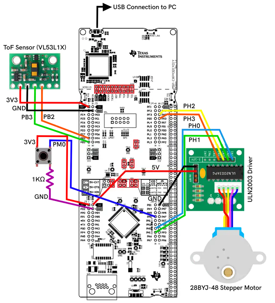
Constructing the device required a thorough understanding of the microcontroller. Below is the circuit schematic used in the project.
Final Product
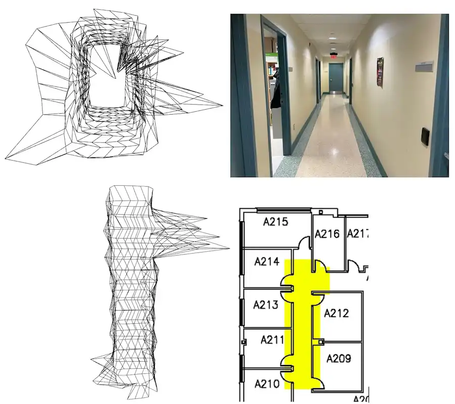
Below are images comparing the line visualizations created using Open3D with photographs of the actual area. Also included is an in-depth technical report and datasheet of the final product.
 Download Datasheet